The correct choice depends on the complete suspended assembly, not the product’s nameplate weight. By measuring the load, tooling, reach, motion, working envelope, utilities, and failure response, you can select the smaller model with confidence or justify the additional reserve of the larger one.
Key takeaways
- Weigh the complete lifted assembly, including the gripper, fixture, hooks, and retained components.
- Record reach, lift height, centre-of-gravity offset, and arm configuration before comparing models.
- Compare payload, moment, speed, footprint, utilities, controls, and failure response—not payload alone.
- Run a real-part trial and document acceptance limits before commissioning the manipulator.
Start With the Complete Lifted Assembly, Not the Part Weight
A 50 kg manipulator has enough usable capacity only when the complete lifted assembly—not just the product—stays inside its load envelope at the actual pick height, horizontal reach, arm configuration, and centre-of-gravity offset. Weigh the part with the gripper, fixture, hooks, clamps, vacuum equipment, and any component retained by the tool.
Then check the capacity chart at that exact position; the headline rating does not apply throughout every working position.
Record these figures before choosing a dra 50 or 80 kgs manipulator:
- Maximum and minimum part weights, including tool mass
- Working radius, lift height, and centre-of-gravity offset
- Required cycle time, acceleration, and pick-and-place path
- Operator force and holding behaviour during utility failure
- Results from repeated cycles with the actual assembly
A 40 kg product uses 80% of a 50 kg manipulator’s nominal capacity, leaving less reserve for offset loading, acceleration, or a heavier variant. An 80 kg manipulator uses 50%, but its additional reserve does not automatically justify higher installation demand, footprint, or running cost.
| Option | Choose it when | Check before approval |
|---|---|---|
| 50 kg manipulator | The assembly stays comfortably below 50 kg and remains close to the arm | Confirm future products will not increase the load |
| 80 kg manipulator | Tooling and product approach 50 kg, the load is offset, handling is dynamic, or heavier variants are planned | Confirm the structure, utilities, and floor space can support it |
Use a Load and Reach Worksheet Before Comparing Models
Record actual geometry and motion, not merely the product’s mass, before opening a capacity chart. A worksheet for an industrial manipulator for factory use must describe the complete lifted assembly at its worst position and fastest intended movement.
- Weigh the product, gripper, fixture, hooks, clamps, vacuum equipment, hoses, and retained parts as one assembly.
- Measure the attachment’s overall length, width, height, and the distance from the arm pivot or mounting axis to the load’s centre of gravity.
- Record pick and place heights, maximum horizontal reach, arm extension, and the required arm configuration at each station.
- Define the motion: lift speed, acceleration, braking distance, swinging, rotation, and any abrupt operator movement during positioning.
- Mark the worst-case orientation, including tilted loads, off-centre gripping, and loads that shift inside a fixture.
- Note the cycle frequency and the starting condition, such as a stationary pick or a moving conveyor.
Use these entries against the chart’s load envelope, not just its headline rating. A 50 kg product on a 50 kg manipulator still exceeds the usable limit after tooling and dynamic loading are added.
At a 0.5 m offset, 50 kg creates about 245 N·m of static moment before acceleration; the chart may restrict that load at a particular height or reach. Record the exact chart conditions and reject any model that passes only at a shorter reach than your process requires.
Compare Payload, Moment, Speed, Footprint, and Running Demand
At 40 kg, a 50 kg manipulator uses 80% of its nominal payload; an 80 kg manipulator uses 50%. The larger model gives more reserve for grippers, fixtures, hooks, clamps, retained product, acceleration, braking, and off-centre loading. A 50 kg part therefore does not automatically fit a 50 kg model.
| Option | Practical difference | Factory consequence |
|---|---|---|
| 50 kg manipulator | Lower reserve and usually lower structural demand | Efficient for compact, repeatable loads that remain well below 50 kg |
| 80 kg manipulator | 60% more rated payload capacity | Better tolerance for heavier tooling, changing products, longer reach, and dynamic loading |
| Either model | Rated capacity applies at a stated reach, centre of gravity, speed, and attachment configuration | Check the capacity chart; capacity can fall as moment increases |
Moment is load multiplied by horizontal distance from the arm’s pivot. A 35 kg assembly at long reach can challenge an industrial manipulator for factory use more than a 45 kg assembly close to the pivot. Record the furthest working radius and the load’s centre of gravity, not only its mass.
| Comparison point | 50 kg model | 80 kg model |
|---|---|---|
| Speed | May feel more responsive with light loads | May need stronger braking and controlled acceleration |
| Footprint | Often easier to fit around a workstation | May need more clearance and stronger support |
| Running demand | Lower air flow and structural demand when correctly sized | Higher peak air consumption and greater load on the mounting structure |
Compare lift speed, lowering speed, horizontal travel, slew range, rotation, braking, and holding at intermediate positions. Verify pressure, flow, hose size, air quality, peak consumption, and behaviour during pressure loss; pneumatic balancing does not remove those utility requirements.
Check the Tool, Controls, Utilities, and Failure Response
A correctly rated manipulator becomes unsafe when its tool, controls, utilities, or failure response do not match the task. Count the gripper, fixture, hooks, clamps, vacuum equipment, and retained product, then allow for acceleration, braking, swinging, off-centre loading, and abrupt operator movement. A 50 kg part is not automatically suitable for a 50 kg rating.
| Option | Check before installation | Consequence if missed |
|---|---|---|
| 50 kg | Tool mass, dynamic reserve, reach, and centre of gravity | Movement becomes heavy, unstable, or overloads the arm |
| 80 kg | Stronger base plate, column, runway, or building attachment | The manipulator transfers excessive vertical load, reaction force, or overturning moment |
| Both | Deadman control, emergency stop, grip-release logic, and operator reach | The load can move or release before the operator can stop it |
For an industrial manipulator for factory use, verify air pressure, flow, hose size, peak consumption, and air quality. Pneumatic balancing does not protect the load when plant pressure falls; movement can become stiff, uncontrolled, or unable to hold position. Check electrical supply and vacuum performance under normal and worst-case conditions.
Specify the response to loss of air, electricity, vacuum, or grip force:
- Load-holding valves, mechanical brakes, or anti-drop devices
- Controlled descent instead of free fall
- A manual recovery procedure that operators can follow without entering the drop zone
Record operator force, lift height, working radius, cycle time, minimum and maximum loads, and repeated-cycle results. “Balanced” is not a safety specification.
Validate the Choice With a Real-Part Trial and Acceptance Record
Do not approve a DRA 50 or 80 Kgs Manipulator from a catalogue demonstration. Ask for a site survey and a witnessed trial using your actual part, fixture, reach, pick-and-place path, and intended cycle rate.
1. Bring the lightest and heaviest production parts, the production gripper, hooks, clamps, vacuum equipment, and every fixture into the trial. Record the total lifted mass, tool mass, centre-of-gravity offset, working radius, pick height, place height, and arm configuration.
2. Check the load-envelope or capacity chart at those exact conditions. The headline rating does not apply across every extension and height; a 50 kg part can exceed usable capacity after tooling, off-centre loading, acceleration, and dynamic forces are included.
3. Run repeated cycles at the required rate, then test slow positioning, load holding, gripping stability, and operator force. Interrupt the air or electrical utility and record whether the load remains supported, moves, or drops.
4. Put the result in an acceptance record: maximum and minimum part weights, cycle time, reach, lift height, force readings, failure-response outcome, cycle count, and every observed fault. Reject the trial if the operator must fight the arm or the tool loses control.
Ask Hendo Industries, or any manipulator supplier in Chennai, to show the mounting reaction and overturning moment calculations before installation. Select the 80 kg manipulator only when its reserve, structure, footprint, or utility demand suits the recorded task better than the 50 kg option.
Related products
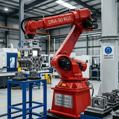
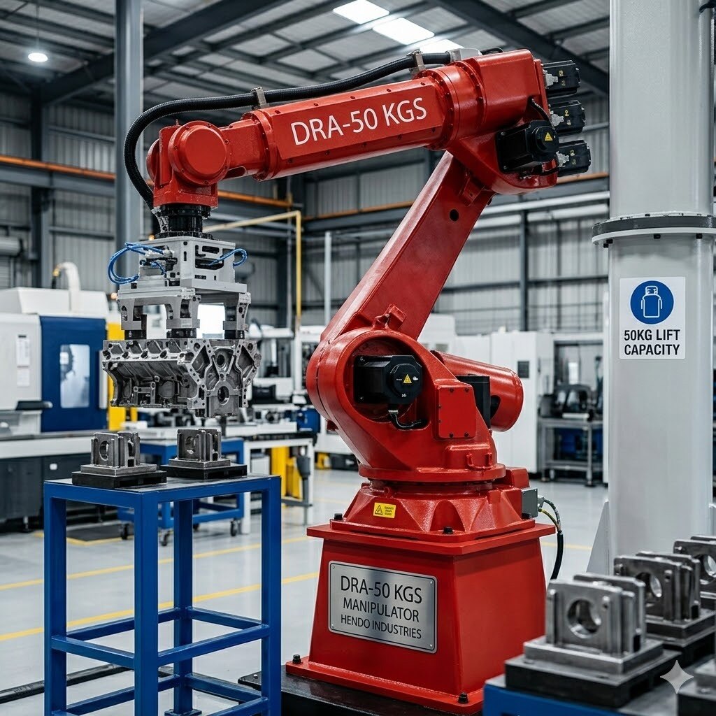
 | Manipulator The DRA-50 KGS Manipulator by Hendo Industries is a versatile and high-performance material handling solution designed to simplify lifting and... View product → |
 | Manipulator The DRA-80 KGS Manipulator by Hendo Industries is a robust and efficient material handling solution designed to streamline industrial operations. View product → |
Frequently asked questions
Should you choose a DRA 50 or 80 kg manipulator based only on part weight?
No. Calculate the complete lifted assembly, including the tool, fixture, hooks, clamps, vacuum equipment, and retained components.
What information belongs on a manipulator load and reach worksheet?
Record assembly weight, pick height, horizontal reach, arm configuration, centre-of-gravity offset, travel, cycle rate, and handling orientation.
Which specifications matter besides payload when comparing a 50 kg and 80 kg manipulator?
Compare load moment, reach, speed, footprint, controls, utility requirements, tool compatibility, running demand, and failure response.
How can you validate the correct industrial manipulator for your factory?
Test the real part with its production tool, then record load, reach, cycle time, operator effort, safety functions, and recovery steps.