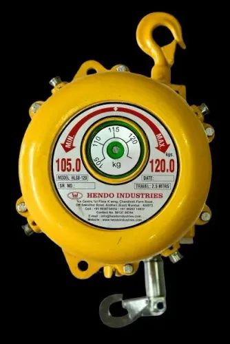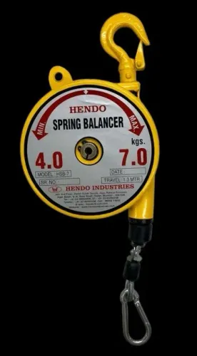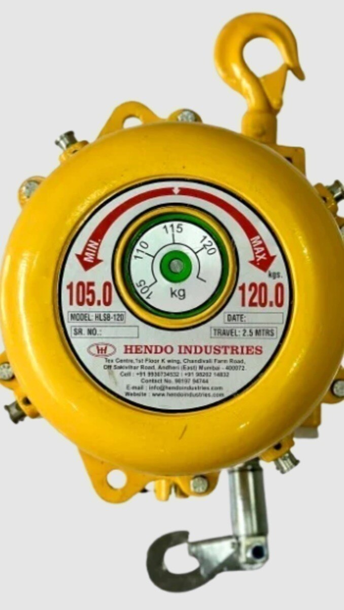
A reach problem exists when an operator cannot place a suspended tool at every required fastening, welding, drilling, or assembly point without fully extending the balancer or pulling its cable sideways. You will be able to measure the workstation, map the real working envelope, diagnose dead zones, and compare a complete tool assembly with the correct balancer range.
Key takeaways
- Measure the longest cable payout and every required tool position.
- Treat sideways cable pull as a reach problem and side-loading risk.
- Compare rated travel and load before choosing an HLSB 22 or HLSB 30.
- Inspect mounting, cable return and tool protection before service.
How to measure a balancer reach problem at a Mumbai automotive workstation
A reach problem is proven when the longest required cable payout from the mounting point to a tool position exceeds the balancer’s rated travel, or the operator must pull the cable sideways to reach that position.
A 2.5-metre spring travel is mainly vertical movement; it is not 2.5 metres of horizontal coverage across a vehicle body.
Measure the workstation in this order:
- Mark every fastening, welding, drilling and assembly point the tool must reach.
- Measure the vertical distance from the balancer mounting point to the lowest required tool position.
- Add the required movement of the operator, fixture or vehicle during the task.
- Measure the actual cable path, including hook and tool length, at the farthest position.
- Compare that total with 2.5 metres, while keeping the cable outlet aligned with the tool and within the manufacturer’s permitted angle.
- Repeat the check from each ceiling, gantry or rail mounting position and mark any unreachable area as a dead zone.
If the farthest point requires more than the available travel, the station fails the reach test. If it fits only when the cable runs diagonally, over a sharp panel edge or around an obstacle, it has a routing or side-loading problem rather than adequate reach.
This is the practical test for sheet metal for balancer reach problems in Mumbai: plot the full tool envelope, not just the balancer label. Route the hose or electrical lead separately so its drag does not corrupt the measurement.
A spring balancer supports a hand tool, not a door, roof panel or coil; use a lifter or hoist for those loads.
What 2.5 metres of sheet metal spring balancer reach actually covers
No: a 2.5-metre cable stroke is predominantly vertical, not 2.5 metres of horizontal travel across a vehicle body or fixture. The figure describes how far the cable can extend from its mounting point; it does not include the hook, tool length, mounting height, or movement along a rail.
Calculate usable reach from the actual suspension point. Measure down to the tool’s lowest required position, then include the tool length and the operator’s required movement around the fixture. Compare that total with the available stroke, while retaining enough cable for the tool to retract without striking the vehicle, press, or overhead structure.
For example, a balancer mounted on a gantry above the centreline can cover fastening points on both sides of a narrow subassembly if the tool remains within its vertical envelope. It leaves dead zones at the outer panels when the operator must pull the tool sideways beyond the mounting point.
A ceiling rail, trolley, boom, or second suspension point supplies horizontal movement; extra cable alone does not.
Side-loading also changes the result. An angled cable rubs against the outlet, increases wear, and pulls the tool back toward the balancer instead of holding it at the panel. Treat “2 point 5 meter sheet metal balancer in Mumbai” as a cable-stroke specification, not a guaranteed work envelope.
Sheet metal spring balancer reach is proven only by mapping every required tool position against the mounted equipment.
Finding dead zones, side-loading and return faults on the line
Mark every fastening, welding, drilling or assembly point on the vehicle body or fixture, then measure from the balancer mounting point to the tool’s lowest required position. Include hook length, tool length and operator movement; compare this vertical travel with the rated cable stroke. A 2.5 m stroke is not 2.5 m of horizontal reach.
A dead zone appears when the tool reaches one side only after the operator pulls the cable diagonally, stretches beyond the rated travel or leans around an obstruction. Stop the line and check these points:
- Mounting position: Move the suspension point temporarily along the rail, gantry or boom. If the unreachable area moves with it, the original position is wrong.
- Obstacles: Trace the tool’s full path around roof rails, press guards, fixtures and vehicle panels. Contact marks or repeated handoffs identify a physical blockage.
- Cable angle: Watch the outlet while the operator works at both sides. A cable that rubs the outlet or stays visibly slanted indicates side-loading.
- Routing: Check whether hoses, whip cables or adapters catch on clamps and edges. A snag followed by a sudden return indicates poor routing.
A return fault occurs when the spring pulls the tool toward the balancer instead of holding it at the work point. Reduce the sideways pull and rerun the path; if the fault remains, reposition the suspension point or use a trolley or boom for the wider envelope.
Keep enough overhead clearance for the tool to retract without striking the vehicle or fixture.
Choosing between an HLSB 22 balancer and HLSB 30 balancer
Choose by the mass of the complete suspended assembly, not the tool’s catalogue weight. Include the tool, chuck or holder, adapters, guards, cable or hose whip, and every accessory that remains attached during operation. A bare drill can fit the lighter unit while the drill, chuck and reaction fixture exceed its working range.
Treat “hlsb 22 balancer” and “hlsb 30 balancer” as model labels, not kilogram ratings. Read the manufacturer’s load-range table and the nameplate before comparing them.
| Option | Compare this | Why it matters |
|---|---|---|
| HLSB-22 | Minimum and maximum supported assembly mass | An assembly below the minimum may not retract; an assembly above the maximum overloads the spring |
| HLSB-30 | Minimum and maximum supported assembly mass | A larger unit can create excessive upward pull on a light drill, riveter or grinder |
| Either model | Rated cable travel and mounting arrangement | The number does not prove horizontal coverage or suitability for your rail, gantry or ceiling point |
| Either model | Hook, brake and protection details on the nameplate | These features affect safe use and cannot be inferred from 22 or 30 |
Weigh the tool exactly as operators use it, then check the balance at the highest and lowest working positions. Hendo Industries can provide the model documentation needed to match that measured assembly to the load range; do not select from the model number alone.
Keep the hose or electrical lead separately routed and strain-relieved. If it wraps around the load cable or rubs on a sheet-metal edge, the operator feels extra drag and the lead can fail before the balancer does.
Choose neither balancer for doors, roof panels or coils. Those loads need a vacuum lifter, hoist, manipulator or positioner.
Related products
 | SHEET METAL SPRING BALANCER HLSB-30 (2.5 MTRS) SHEET METAL SPRING BALANCER The HLSB-30 (2.5 MTRS) Sheet Metal Spring Balancer by Hendo Industries is a robust and efficient industrial tool balancing solution designed to... View product → |
 | SHEET METAL SPRING BALANCER HLSB-22 (2.5 MTRS) SHEET METAL SPRING BALANCER The HLSB-22 (2.5 MTRS) Sheet Metal Spring Balancer by Hendo Industries is a durable and high-performance industrial balancing solution designed for... View product → |
Mounting, protection and inspection before putting the balancer into service
A balancer is ready for service only when its support can carry the suspended assembly and the forces created by movement, not just the tool’s weight. A light sheet-metal bracket is not an acceptable substitute for a rated eye bolt, beam clamp, trolley, boom, or cantilever.
1. Verify the beam, rail, trolley, or cantilever is rated for the balancer, hook, tool, hoses, and foreseeable dynamic loading. Check fasteners, welds, clamps, and anchor points for looseness, distortion, cracking, or corrosion.
2. Inspect the sheet-metal work area for sharp edges, burrs, pinch points, weld spatter, and obstructions. Route the cable so it does not rub against a panel or outlet; side-loading increases wear and pulls the tool back toward the balancer instead of holding it at the work point.
3. Confirm the mounting height and cable travel place the tool at every required position without reaching the travel stop. Include hook length, tool length, operator movement, fixture height, and overhead clearance; cable length alone does not prove usable reach.
4. Fit positive secondary retention above occupied work areas. Use an independently anchored, rated tether or safety device; do not treat the balancer’s primary hook, clamp, trolley, or fabricated line structure as the only dropped-tool protection.
5. Complete the manufacturer’s inspection and maintenance schedule before release. Examine the cable, hook, housing, spring action, fasteners, and return movement, then record defects and remove the unit from service if it binds, frays, or fails to retract correctly.
Use a vacuum lifter, hoist, manipulator, or pneumatic or hydraulic positioner for doors, roof panels, coils, and other parts. A spring balancer supports a hand tool, not sheet metal.
Frequently asked questions
How do you measure a balancer reach problem at a Mumbai automotive workstation?
Measure from the mounting point to the farthest required tool position, then compare that cable payout with the balancer’s rated travel. Record any position that requires sideways cable pull.
What does 2.5 metres of sheet metal spring balancer reach cover?
It covers tool positions within 2.5 metres of the mounting point along the cable’s usable path. It does not guarantee safe reach when the operator must pull the cable sideways.
How can you find dead zones, side-loading and return faults?
Map every tool position, watch for locations the cable cannot reach without lateral force, and check whether the cable returns smoothly after release.
How do you choose between an HLSB 22 balancer and an HLSB 30 balancer?
Compare each model’s rated travel and supported tool load with the workstation’s longest payout, tool weight and operating path before selecting one.
What must you inspect before putting a balancer into service?
Check the mounting structure, fasteners, cable path, protective features, tool attachment and return action before allowing production use.